|
Thick Plate Laser Cutting

by Brian J. Jarvis
The advancement in recent years of higher power lasers has increased companies' abilities to expand beyond the gauge material barrier and process thicker plate more efficiently. Higher power lasers are now able to process thicker plate up to 1 1/4" thick. These lasers typically can average power output ranging from 3000W up to 6000W. It is unlikely that high power lasers will replace the plasma or oxy fuel process, but they do provide the ability to produce more precise parts with a minimal heat effect zone (HAZ). The ability to process thick material has placed greater demands on both the machine tool manufacturers, and end uses alike. From the manufacturing perspective, machine tools and laser resonators which were typically 1000W - 2000W, and were designed to deal with thinner material, are being replaced by market demands with the higher power resonators. Machine and material handling design and implementation have caused some manufacturers to completely re-evaluate their machine and control/software designs to cope with more demanding CNC processing parameters as well as the increase in material weight and handling flexibility.
From the end user's perspective, many are experiencing frustration at the lack of ability to cut thicker plate consistently. Around 10-12 years ago the maximum capacity many companies were able to process was HRPO (Hot Rolled Pickled Oiled) steel. The purpose of this paper is to hopefully provide some insight for new and current laser users who are considering branching out into the high power laser market, and point out some of the potential problems in processing plate on a consistent basis.
Typically a potential user will purchase a laser based on the manufacturers specifications, to process for example " mild steel. After making such an investment, once the system is installed they typically will wish to take a piece of plate stock and begin producing parts immediately in ". When they are unable to produce quality parts on a consistent basis they become frustrated. To achieve satisfactory results in plate material, emphasis must be placed on the items covered in this article irrespective of the equipment manufacturer. Doing so should ensure more reliable results. The margin for error becomes increasingly smaller in thicker material, and compromising any of the laser cutting parameters will result in less than desirable results. Operator experience is extremely important, and gaining the necessary comfort to deviate from the manufacturer's installed cutting parameters takes time. There is no short cut for experience; therefore many companies tend to achieve better results after 2-3 months of operation behind them.
Acceptable Quality
To many customers acceptable quality is achieving a consistent part run, with straight parallel edges, with the minimal of angular deviation. These parts should be produced with fine striations and no burnouts and with minimal dross. Part tolerance with minimal heat effect zone (HAZ) and kerf width over the entire work envelope are also required. To better understand what is required to achieve this on a regular basis we must look at some of the key parameters.
Optics
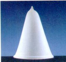
The mode of the laser must remain stable and symmetrical (Example # 1) and remain linearly consistent throughout the entire power curve of the resonator. This is very often a reflection of the quality of the laser source and optical delivery system. An asymmetric mode will vastly influence the laser cutting conditions and cause differing cut quality, depending on the direction of travel.
Example # 1
The resonator must also have an accurate pointing stability. The beam delivery optics must be clean and well aligned. And the focusing lens must be clean and correctly aligned to the nozzle. Larger table machines (12', 20', 50' tables) may require the use of one of the following to ensure the minimal amount of divergence (beam spread in milli radians/meter) influence, and to ensure that the laser beam is always impacting the cutting lens in the same surface area.
- Beam expander/collimator, an optical device, usually comprising of either two lenses or a concave and convex mirror in the external machine beam delivery system.
- Adaptive optics, a deformable mirror that can flex normally from -10um to + 30um. Very often the cutting table is divided into "theoretical zones": when the laser cutting head passes within these zones the mirror is placed in a concave or convex arrangement, expanding or collimating the beam as necessary.
- A beam compensation axis, often an independent axis that moves in proportion to the cutting head movement, keeping the beam length consistent.
Assist Gas
One must not underestimate the function of the assist gas; this is key to speed and edge quality. The role of oxygen in the cut process has three basic functions:
- It provides chemical energy into the cutting zone by providing exothermic reaction of iron-to-iron oxide. The laser beam/material absorption coefficient of the respective plate determines the rate or amount of interaction (reflection / absorption) between the beam and material. The laser typically contributes approximately 60% of the energy in the cut process with the oxygen doing 40%.
- It provides mechanical energy to expel the oxidized molten material.
- As a free flowing gas it also to serves to cool the cut zone by means of forced convection.
The purity of oxygen can vastly increase the speed and edge quality; speeds in some cases may be increased by as much as 15% just by switching from 99.95% grade to 99.998%. Higher purity oxygen also has a direct bearing on the overall edge quality. Impurities and Hydrocarbons in the oxygen stream serve to suppress its role and efficiency. Sufficient oxygen must flow into the cut zone and is directly proportional to the flow of molten material expelled from the cut zone, and can be expressed by the following:
Mf=kvdr
Where Mf = material mass in the oxidization
k = kerf width
v = cutting head velocity
d = material thickness
r = Material densityThe reaction of the material relative to laser absorption and thus the thermal conductivity of the part is directly dependent upon on the Irradiance (laser power W/cm2).
The machine tool must also have a very stable gas proportion valve that is capable of withstanding the high pressures of Nitrogen, cutting normally up to 20-30 bar for Stainless Steels, and still remain stable at the low pressures required for oxygen cutting of thick plate. A good starting point for programmed assist gas pressures for thicker plate typically start around 0.4-0.6 bar. Adjustments in increments of 0.1 bar up or down should be made until the satisfactory cut is achieved. Deviations from this by around 0.15 bars could make the difference in achieving the cut or not. Increasing the nozzle diameter also will reduce the gas pressure but often leaves the cutting lens more susceptible to splatter caused by rapid piercing. Too little gas flow can cause damage to the lens and may not be sufficient enough to expel the molten material through the kerf. Too little gas flow can also increase the heat build up during piercing. Nozzles from 2mm to 3mm produce the most satisfactory results when used with the above gas pressures. Nozzle design has undergone many changes in recent years and remains for some manufacturers a closely guarded secret. Nozzle material, angularity, surface finish, length of taper etc cannot be over simplified, and remains a key variable in process speeds and quality. Experiments with different nozzles have shown dramatic changes in the process.
Material Quality
The material quality cannot be overlooked; this is all too often the most common cause of cutting problems. In Europe and Japan companies have access to "laser grade" material. In the USA we do not have that privilege and are often left with A36. A36 is not a bad grade of material, but it does however come in a broad spectrum of quality and consistencies. One of the biggest problems in laser cutting is adjusting your plate parameters for a batch of material; you cut just fine, but when the next batch of material is to be processed you cannot cut it utilizing the same parameters used previously. This very often results in inconsistent mill runs and carbon / silicon composition. The closest to "laser grade" material we have in the USA is A572 or A514B and HRPO. If A36 is to be processed emphasis must be placed on the material consistency, and as with all plates the surface must be free from rust and mill scale. HRPO is quite often the preferred material quality over plain black hot rolled plate. Black hot rolled is merely material that is normally transferred at high temperatures in billets through a series of rolls. During this process the plate is often subjected to air/and water, used to cool or lubricate the rolls. The plate therefore is very often covered by a thick layer of oxides. By contrast HRPO is simply hot rolled plate that has had the oxide from the surface removed by chemical etching (pickling). Oil is then applied to the surface to prevent future rusting. Rust (iron oxide) on the plate can contain trace amounts of moisture. When absorbed by the laser beam boils off producing steam, this in turn reacts with the oxygen assist gas, greatly impeding the Oxygen's ability to assist in the cut process. This will typically cause melt out in certain areas of the parts. In recent years, a manufacturers brand A36 City steel has yielded excellent cutting results. A typical chemical composition chart can be seen in Example # 2.
Example # 2
C MN P S SI CU NI CR MO SN AL V Nb 0.08 0.87 .007 .026 .20 .273 .155 .099 .045 .02 .005 0 .002 Shot blasting of the material with sand can remove surface oxides but tends to impregnate the surface with very fine grains of sand. Doing so causes an interaction with the laser beam, producing silica. This tends to change the chemical interaction of the oxygen assist gas with the material, yielding poor results and localized over melting of the plate. Shot blasting by steel can often improve the cut quality, providing the indents are not too severe.
Piercing
Several types of piercing techniques are employed, ranging from rapid or blast piercing, to pulse piercing. Rapid piercing, as the name suggests, will blow through the material in seconds. However, this can cause splatter which can result in damage to the cutting lens. In addition the "crater" effect left in the material often damages the desired contour. The molten metal left on the surface, if not removed, can cause collisions with the machine tools sensing system, be capacitive or contact type. Pulse piercing techniques provide a solution by allowing a cool down period between pulses, minimizing heat effect, and pierce entry size. However it takes much longer to pierce the material. The advents of new pierce detection systems provide a way to sense when the pierce has taken place and commence cutting immediately. This saves on wasted time the laser has to spend on varying times it takes to pierce the plate in different locations based on material consistency. Pierce detection also prevents the heating up of dross under the table left by previous cuts. Pulse pierce frequencies are best programmed around 80-130HZ with automatic pulse increments around 20% - 35%. Smaller holes may require pulse duty cycles around 30-50%.
Pulse Cutting VS CW (Continuous Wave)
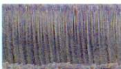
It should be noticed that during thick plate cutting, striations can be noticed along the top edge of the plate and towards the middle to lower section these striations become much smoother. The material absorbs the laser energy in the upper portion of the plate, with a focal point setting typically on or above the material surface. The lower smoother edge is the result of the molten material flow ejection caused by the assist gas "blow" effect. The roughness of the upper edge of the plate when cut with CW is typically the result of many differing variables, plate quality been the most common. The upper edge condition may be altered by pulsing the laser, typically around 200-600hz with a duty cycle of around 80-95%, during the cutting process. This serves to allow the material to cool more rapidly, resulting in finer striations; this in turn gives the appearance of a finer edge. Pulse cutting is also less susceptible to resonant shock waves created by the assist gas at higher feed rates. Example # 3 shows a " plate cut in CW and Example # 4 a " plate cut during pulsing.
Example # 3
Example # 4
Corner Control
Most CNC machines to date offer some type of corner edge control, or power ramping cycle. Example # 5 shows a typical problem that is caused when the cutting head changes direction and has not allowed the lagging expelled molten material time to catch up. This causes the lower portion of the edge to melt away. Power ramping or corner dwelling, serve to allow the cutting head to either reduce its speed in proportion to the laser power and/or dwell for a given period of time normally only mil seconds. This allows the trailing ejecting material time to catch up, before a direction change is made. Newer and more specialized "look ahead angle" features are been implemented all the time, as the dwell, ramping function is often a fine window for an operator to stay within, and can change with differing material grades. Dwelling too long can cause a greater HAZ in the part. One problem that is all too often overlooked in plate cutting is the sheer weight of the parts after the cut has completed. Emphasis must also be placed on the cutting table grid design, as well as part placement with respect to the grids if possible. Once the cut is in its final stages the part may have a tendency to drop, this also can cause corner damage during the final seconds of the cut.
Example # 5
Focus Types and Position
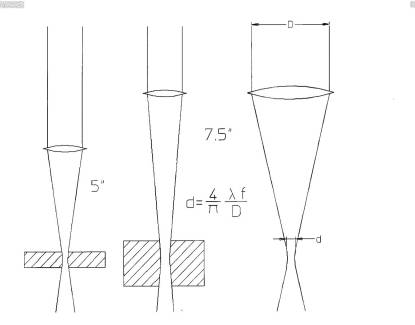
With thicker plate processing 7.5" to 10" lenses are most commonplace. They provide a larger spot size to allow the molten material to be expelled, and provide a greater depth of field for edge angularity. The spot size (d) is a function of the incoming beam diameter (D), the focal length (f) and wavelength of the laser (l), d= 4/p lf/D. A good example of the difference between a conventional 5" lens commonly used for gauge processing up to 0.25, and the 7.5" lens typically utilized for plates up to ", can be seen in Example # 6.
The focus position is often placed on or slightly above the material surface, this provides the best edge quality, but does not provide the most energy in the material. When using new automatic focusing systems the focus position can be lowered into the material for piercing, providing faster pulse pierce times and minimal HAZ. Automatically adjusted back for the optimal cutting position. Utilizing low pulse frequencies around 80 - 700 HZ with a Duty Cycle of 80 - 95% minimal heat will be induced in the part. With a 7.5" focal lens a laser can typically produce a spot size of 0.006 - 0.0010" and a 0.014" - 0.018" kerf width.
Example # 6
Software
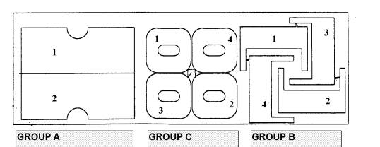
Parts must be nested and processed so as to minimize the heat effect zone in the material, affecting the material tensile on the next part to be processed. Parts should be cut in alternate group sequence (A) and then alternated to the next part (C) then (B). Individual parts should also be alternated between, depending on part contour for example 1,2,3,4. Common line cutting is not well suited for thick plate due to heat transfer to the surrounding parts. It should also be recognized that while a good rule of thumb of 1:1 or material thickness versus smallest hole or contour etc is acceptable in thinner material, a 2 or 2.5:1 ratio should be observed in thicker plate. While most laser operators are very often able to reduce this ratio of 1:1 in thinner material to sometimes 0.4:1, this is not the best solution for achieving consistent results in plate processing in a production environment. Therefore care in selection of part contours for laser processing should be reviewed. Webb thickness between nested parts must be equal to or greater than the material thickness. In addition it is advisable to review software that allows the operator to be manually able to change the cut sequence. Example # 7 shows a typical nest of parts and recommended cut sequence and grouping of parts to minimize the HAZ and influence on surrounding parts.
Example # 7
Water/Oil assisted Cutting
The use of a mist and/or water/oil can provide a cooling effect to the material, and in some cases shorten the time operators may take to develop processing specific parameters. Testing has shown that dross, sometimes apparent with poor quality material, is sometimes reduced by the use of water/oil mixture. This is particularly true in the case of steel with higher manganese content. The use of coolant however is not without its drawbacks. Using this technique can also cause beam dispersion and influence the overall cut edge quality. Rusting of the material can also occur if not removed. This process typically adds a second operation to the part. In addition the mixture of excessive water/oil and metal particles forms an abrasive compound, which rapidly destroys scrap removal conveyors and prohibits the use of non-contact or capacitive height sensors.
Click here to find suppliers
|
|
| Home | About Us | Back To Technical Library | Contact Us |
|
Copyright © 1996-2010 JobShop.com. All Rights Reserved. General or Technical Questions? E-mail support@JobShop.com |